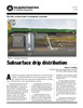
 A subsurface drip distribution system distributes wastewater through a system of tubing with flow regulating emitters. The tubing can be installed at various depths below the ground surface. It generally consists of six main components:
• Pump and controls
• Flow metering device
• Filtering device
• Drip distribution field
The pump tank stores the treated wastewater until it is dosed. A high-head pump delivers the water from the pump tank through the filtering device to the drip distribution system.
A control system regulates dosing to the drip fields. Most systems utilize a control panel to implement time-dosing to the fields. This allows effluent to be distributed throughout the day in even doses. Control panels can also control automatic filter backwashing and field flushing. Some systems use demand-dosing to the drip fields with a manual filter and field flushing, but this is not recommended.
The filtering device can be a sand filter, disk filter, or screen filter. Its main purpose is to remove larger particles from the wastewater so they do not plug the drip emitters. Depending on the system design, the filter may have an automatic backwash for the filter devices that can be activated by pressure differentials before and after the filter or on a predetermined frequency. The system can also have automatic, manual, and continuous field flushing.
Flow metering incorporated into the system facilitates monitoring of total hydraulic loading to the drip fields. This flow metering can be accomplished through use of a flow meter, elapsed time meter, or cycle/event counters. Flow meters provide a direct measure of flow. Elapsed time meters and cycle/event counters require the dose volume or pump flow rate for calculating the flow to the fields. Flow meters can also be used to measure flow rate to the drip fields by recording the volume dosed during a given period of time.
The drip distribution system is made of drip tubing approved by the manufacturer for use with wastewater. The tubing is generally ½ inch in diameter with an emitter sonically welded in the tubing wall. The pressure inside the tubing is generally operated at 15 to 70 pounds per square inch (psi), with the water exiting the emitter at 0 psi.
A drip field consists of drip tubing placed along the contour to form a run of tubing. These runs can be connected directly to the supply and return manifold forming a “ladder type” drip zone. The individual runs can be looped together to form a lateral. These laterals can then be connected to the supply and return manifold on the same end or opposite ends of the zones. A run is identified as one drip line along the length of the zone while a lateral is defined as one drip line from the supply manifold to the return manifold. There can be multiple runs per lateral.
Related Resources:
 Operation and Maintenance Checklist: Drip Distribution
 Subsurface Drip Distribution (and in Spanish)